- 您现在的位置:买卖IC网 > Sheet目录629 > PAXCDL10 (Red Lion Controls)ANALOG OUTPUT CARD
�� �
�
�COMMAND� RESPONSE� TIME�
�SERIAL� TIMING�
�The� meter� can� only� receive� data� or� transmit� data� at� any� one� time� (half-duplex�
�operation).� During� RS232� transmissions,� the� meter� ignores� commands� while�
�transmitting� data,� but� instead� uses� RXD� as� a� busy� signal.� When� sending�
�commands� and� data� to� the� meter,� a� delay� must� be� imposed� before� sending�
�another� command.� This� allows� enough� time� for� the� meter� to� process� the�
�command� and� prepare� for� the� next� command.�
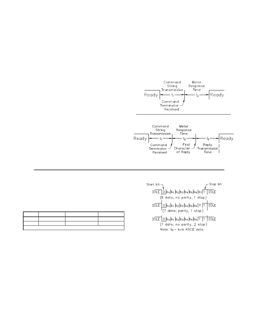
�At� the� start� of� the� time� interval� t� 1� ,� the� computer� program� prints� or� writes� the�
�string� to� the� com� port,� thus� initiating� a� transmission.� During� t� 1� ,� the� command�
�characters� are� under� transmission� and� at� the� end� of� this� period,� the� command�
�terminating� character� (*,� $� or� slave� only� <CR>)� is� received� by� the� meter.� The�
�COMMAND�
�R�
�#�
�V�
�T�
�P�
�COMMENT�
�Numeric� Slave�
�Reset�
�Literal�
�Write�
�Transmit�
�Print�
�PROCESS� TIME� (t� 2� )�
�2-50� msec.�
�2-50� msec.�
�2-50� msec.�
�100-200� msec.�
�2-50� msec.� for� $�
�50-100� msec.� for� *� and� <CR>�
�2-50� msec.� for� $�
�time� duration� of� t� 1� is� dependent� on� the� number� of� characters� and� baud� rate� of�
�the� channel.�
�t� 1� =� (10� times� the� #� of� characters)� /� baud� rate�
�At� the� start� of� time� interval� t� 2� ,� the� meter� starts� the� interpretation� of� the�
�command� and� when� complete,� performs� the� command� function.� This� time�
�interval� t� 2� varies� (See� Timing� Diagrams).� If� no� response� from� the� meter� is�
�expected,� the� meter� is� ready� to� accept� another� command.�
�If� the� meter� is� to� reply� with� data,� the� time� interval� t� 2� is� controlled� by� the� use�
�of� the� command� terminating� character.� The� ‘*’� or� ‘<CR>’� terminating� character�
�results� in� a� response� time� window� of� 50� msec.� minimum� and� 100� msec.�
�maximum.� This� allows� sufficient� time� for� the� release� of� the� sending� driver� on�
�the� RS485� bus.� Terminating� the� command� line� with� ‘$’� results� in� a� response�
�time� window� (t� 2� )� of� 2� msec.� minimum� and� 50� msec.� maximum.� The� faster�
�response� time� of� this� terminating� character� requires� that� sending� drivers� release�
�within� 2� msec.� after� the� terminating� character� is� received.�
�At� the� beginning� of� time� interval� t� 3� ,� the� meter� responds� with� the� first�
�character� of� the� reply.� As� with� t� 1� ,� the� time� duration� of� t� 3� is� dependent� on� the�
�number� of� characters� and� baud� rate� of� the� channel.� At� the� end� of� t� 3� ,� the� meter� is�
�ready� to� receive� the� next� command.�
�t� 3� =� (10� times� the� #� of� characters)� /� baud� rate�
�The� maximum� serial� throughput� of� the� meter� is� limited� to� the� sum� of� the�
�times� t� 1� ,� t� 2� and� t� 3� .�
�COMMUNICATION� FORMAT�
�Data� is� transferred� from� the� meter� through� a� serial� communication� channel.�
�In� serial� communications,� the� voltage� is� switched� between� a� high� and� low� level�
�at� a� predetermined� rate� (baud� rate)� using� ASCII� encoding.� The� receiving� device�
�reads� the� voltage� levels� at� the� same� intervals� and� then� translates� the� switched�
�levels� back� to� a� character.�
�The� voltage� level� conventions� depend� on� the� interface� standard.� The� table�
�lists� the� voltage� levels� for� each� standard.�
�50-100� msec.� for� *� and� <CR>�
�Timing� Diagrams�
�NO� REPLY� FROM� METER�
�RESPONSE� FROM� METER�
�LOGIC�
�1�
�0�
�INTERFACE� STATE�
�mark� (idle)�
�space� (active)�
�RS232*�
�TXD,RXD;� -3� to� -15� V�
�TXD,RXD;� +3� to� +15� V�
�RS485*�
�a-b� <� -200� mV�
�a-b� >� +200� mV�
�*� Voltage� levels� at� the� Receiver�
�Data� is� transmitted� one� byte� at� a� time� with� a� variable� idle� period� between�
�characters� (0� to� ?� ).� Each� ASCII� character� is� “framed”� with� a� beginning� start� bit,�
�an� optional� parity� bit� and� one� or� more� ending� stop� bits.� The� data� format� and�
�baud� rate� must� match� that� of� other� equipment� in� order� for� communication� to�
�take� place.� The� figures� list� the� data� formats� employed� by� the� meter.�
�Start� bit� and� Data� bits�
�Data� transmission� always� begins� with� the� start� bit.� The� start� bit� signals� the�
�receiving� device� to� prepare� for� reception� of� data.� One� bit� period� later,� the� least�
�significant� bit� of� the� ASCII� encoded� character� is� transmitted,� followed� by� the�
�remaining� data� bits.� The� receiving� device� then� reads� each� bit� position� as� they� are�
�transmitted.�
�27�
�Character� Frame� Figure�
�Parity� bit�
�After� the� data� bits,� the� parity� bit� is� sent.� The� transmitter� sets� the� parity� bit� to�
�a� zero� or� a� one,� so� that� the� total� number� of� ones� contained� in� the� transmission�
�(including� the� parity� bit)� is� either� even� or� odd.� This� bit� is� used� by� the� receiver�
�to� detect� errors� that� may� occur� to� an� odd� number� of� bits� in� the� transmission.�
�However,� a� single� parity� bit� cannot� detect� errors� that� may� occur� to� an� even�
�number� of� bits.� Given� this� limitation,� the� parity� bit� is� often� ignored� by� the�
�receiving� device.� The� PAX� meter� ignores� the� parity� bit� of� incoming� data� and�
�sets� the� parity� bit� to� odd,� even� or� none� (mark� parity)� for� outgoing� data.�
�Stop� bit�
�The� last� character� transmitted� is� the� stop� bit.� The� stop� bit� provides� a� single� bit�
�period� pause� to� allow� the� receiver� to� prepare� to� re-synchronize� to� the� start� of� a�
�new� transmission� (start� bit� of� next� byte).� The� receiver� then� continuously� looks�
�for� the� occurrence� of� the� start� bit.� If� 7� data� bits� and� no� parity� is� selected,� then� 2�
�stop� bits� are� sent� from� the� PAXI.�
�发布紧急采购,3分钟左右您将得到回复。
相关PDF资料
PAXLC800
COUNTER 8-DIGIT BI-DIR COUNT
PAXLPT00
METER PROCESS TIME 6-DIGIT
PAXLR000
METER RATE INDICATION 6-DIGIT
PB52233SLK
PROJ BOARD COLDFIRE M52
PD412411
DIODE MOD ISO DUAL 2400V 1100A
PF24-30
TRANSFORMER LO PRO 15VAC 1.6A
PFT12-28
TRANSFORMER 16VCT 28VCT 12VA
PFT12-35
TRANSFORMER 16VCT 35VCT 12VA
相关代理商/技术参数
PAXCDS10
功能描述:DUAL POINT RELAY OUTPUT CARD RoHS:是 类别:继电器 >> 配件 系列:PAXCDS 其它有关文件:Declaration of Conformity 标准包装:1 系列:- 附件类型:散热片 技术规格:3.5° C/W 适用于相关产品:Multiple 系列 颜色:-
PAXCDS20
制造商:Red Lion Controls 功能描述:Card, Plug-In; + 0.01% 10 ms; Quad Setpoint Relay Output Card; PAX Series 制造商:Red Lion 功能描述:Bulk 制造商:Red Lion Controls 功能描述:QUAD RELAY CARD 制造商:Red Lion Controls 功能描述:OUTPUT MODULE RELAY 制造商:Red Lion Controls 功能描述:OUTPUT MODULE, RELAY 制造商:Red Lion Controls 功能描述:QUAD SETPOINT RELAY OUTPUT INTERFACE CARD; Accessory Type:Quad Setpoint Relay Output Interface Card; For Use With:Red Lion PAX Digital Input Panel Meters ;RoHS Compliant: Yes
PAXCDS30
制造商:Red Lion Controls 功能描述:Panel Meter, OptionCard for Dual Rate Totalizer, Quad Setpoint Sinking Output 制造商:Red Lion Controls 功能描述:QUAD NPN-OC CARD
PAXCDS40
制造商:Red Lion Controls 功能描述:Card, Plug-In; + 0.01% 10 ms; PAX Series 制造商:Red Lion Controls 功能描述:QUAD PNP-OC CARD 制造商:Red Lion Controls 功能描述:SOURCING OPEN COLLECTOR OUTPUT INTERFACE CARD; Accessory Type:Quad Setpoint Sourcing Open Collector Output Interface Card; For Use With:Red Lion PAX Digital Input Panel Meters ;RoHS Compliant: NA
PAXCK000
制造商:Red Lion Controls 功能描述:Timer; Red, Sunlight Readable; 0.56 in.; 18 VA; 85 to 250 VAC; 2300 V (RMS) 制造商:Red Lion Controls 功能描述:CLOCK/TIMER FIELD UPGRADEABLE 制造商:Red Lion Controls 功能描述:DIGITAL MULTIFUNCTION TIMER RTC 制造商:Red Lion Controls 功能描述:DIGITAL MULTIFUNCTION TIMER, RTC 制造商:Red Lion Controls 功能描述:DIGITAL MULTIFUNCTION TIMER; Supply Voltage Range:85V AC to 250V AC; Time Min:0.001s; Time Max:1h; Power Consumption:18VA; Panel Cutout Height:45mm; Panel Cutout Width:92mm; Character Size:0.56"; Display Font Color:Red ;RoHS Compliant: NA 制造商:Red Lion Controls 功能描述:DIGITAL MULTIFUNCTION TIMER, RTC; Supply Voltage Range:85V AC to 250V AC; Time Min:0.001s; Time Max:1h; Power Consumption:18VA; Panel Cutout Height:45mm; Panel Cutout Width:92mm; SVHC:No SVHC (19-Dec-2012); Count Speed Max:50Hz; ;RoHS Compliant: Yes
PAXCK010
制造商:Red Lion Controls 功能描述:CLOCK/TIMER, FIELD UPGRADEABLE RED DC 制造商:Red Lion Controls 功能描述:DC CLOCK/TIMER FIELD 制造商:Red Lion Controls 功能描述:DIGITAL MULTIFUNCTION TIMER RTC 制造商:Red Lion Controls 功能描述:DIGITAL MULTIFUNCTION TIMER, RTC 制造商:Red Lion Controls 功能描述:DIGITAL MULTIFUNCTION TIMER; Supply Voltage Range:11V DC to 36V DC; Time Min:0.001s; Time Max:1h; Power Consumption:14W; Panel Cutout Height:45mm; Panel Cutout Width:92mm; Character Size:0.56"; Display Font Color:Red ;RoHS Compliant: NA
PAXCK100
制造商:Red Lion Controls 功能描述:CLOCK/TIMER, FIELD UPGRADEABLE GREEN 制造商:Red Lion Controls 功能描述:CLOCK/TIMER FIELD UPGRADEABLE
PAXCK110
制造商:Red Lion Controls 功能描述:CLOCK/TIMER, FIELD UPGRADEABLE GRN DC 制造商:Red Lion Controls 功能描述:DC CLOCK/TIMER FIELD UPGRADEABLE